A composite slab subjected to furnace fire
Developed by Qiu Jin and Dr Liming Jiang (This example is uncompleted)
Introduction
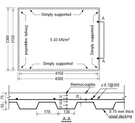
Figure 1 shows the slab configuration, which was tested by BRANZ using a furnace (Lim et al., 2002). This is a composite slab tested in New Zealand. A UDL of 5.4kN/m2 was loaded on the slab during the fire test, and the fire following the standard time-temperature curve lasted for 3 hours. An enhanced version of LayerShellThermal section is used in this model, which enables unified reference plane to significantly reduce the modelling efforts by eliminating the elements for ribs.
| OpenSees Model | Type used for this example |
|---|---|
| Element | ShellNLDKGQThermal |
| Section | LayeredShellThermal (V2.0) |
| Material | CDPPlaneStressThermal, SteelECThermal, J2PlaneStressThermal |
| Thermal Loading | ShellThermalAction, with userdefined dat file |
Download: This Example Package
Model Geometry
Tcl scripts for model definition
model BasicBuilder -ndm 3 -ndf 6;

#define model parameters: Number of elements along x and y, slab dimensions, UDL

set nx 20;

set ny 20;

set slabT 0.1;

set slabB 3.150;

set slabL 4.150;

set UDL 5.4E3;


#define material models

set gt [expr 3.7e6/2.2e10*3.7e6*2];

set gc [expr 37.0e6/2.2e10*37.0e6*6];

nDMaterial  CDPPlaneStressThermal 100 2.2e10 0.2 3.7e6 37e6 $gt $gc;

nDMaterial   PlateFromPlaneStressThermal    4   100   1e9;


#uniaxialMaterial SteelECThermal 1 EC2NC 5.65e8 2e11;

uniaxialMaterial SteelECThermal 1 EC2NH 4.68e8 2e11;

nDMaterial PlateRebarThermal 3 1 0;

nDMaterial PlateRebarThermal 5 1 90;

nDMaterial  J2PlaneStressThermal 13 21 2e11 0.3 4.68e8 6.00e8 0.1 2e8;

nDMaterial   PlateFromPlaneStressThermal    46   13   20e10;


#define shell section:rebar/layer

section LayeredShellThermal   5  13 4  0.008 4  0.008  4 0.008435 3 0.000565 5 0.000565 4 0.004435  4  0.01 4  0.01 4  0.01 4  0.01 4  00.01 4  0.01 4  0.01 ;

section LayeredShellThermal   6  12 4  0.01 4  0.01  4 0.005 46 0.000565 4 0.004435 4  0.01 4  0.01 4  0.01 4  0.01 4  0.01 4  0.01 4  0.01 ;


#define shell elements using block2d

block2D $nx $ny 1 1 ShellNLDKGQThermal  5 {

    1   0. 0. 0.

    2   4.15 0. 0.

    3  4.15 3.15 0.

    4   0. 3.15 0.

}


#define boundary condition:simply supoorted;

fixX 0  0 0 1 0 0 0 ;

fixX 4.15  0 0 1 0 0 0 ;

fixY 0  0 0 1 0 0 0 ;

fixY 3.15  0 0 1 0 0 0 ;

fix 1  1 1 1 0 0 1 ;


#Define recorders

#DisplayModel3D  DeformedShape $ViewScale $xLoc1 $yLoc1  $xPixels $yPixels

set MidEle [expr 1+($nx)*$ny/2+$nx/2];
Output Results
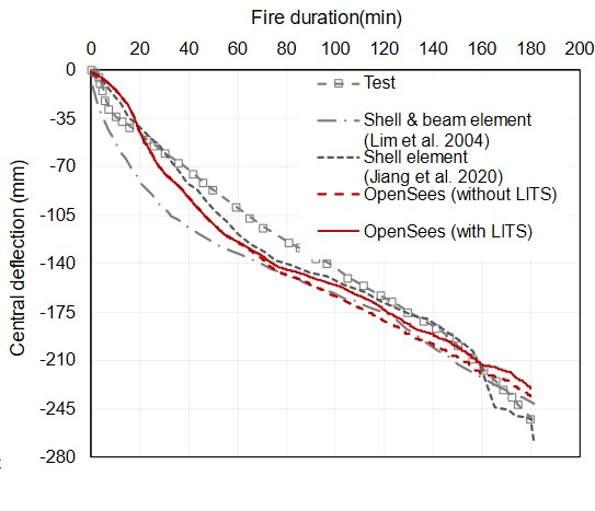
The varation of the mid-node displacement is shown in the following figure
Jiang, L. et al. (2021) ‘Modelling concrete slabs subjected to fires using nonlinear layered shell elements and concrete damage plasticity material’, Engineering Structures. Elsevier Ltd, 234i, p. 111977. doi:10.1016/j.engstruct.2021.111977.
Qiu et al. 'A unified approach for modelling composite slabs in fire", Engineering Structures (under review)
This page is created by Liming Jiang, 2016