Simply supported plate subject to experimental temperatures
Developed by Mhd Anwar Orabi
Introduction
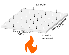
Simply supported slab with 100 mm depth and a plan of 4.15 m × 3.15 m as shown in Figure E6-1 subject to distributed load of 5.4 kN/m2. 25 mm concrete cover is applied over a steel area of 295 mm2/m. Concrete has a compressive strength of 37 MPa, and a tensile strength of 0.1×f’c. Crushing strain of the concrete is 0.0025, and steel yields at 568 MPa and has a Young’s modulus of 206 GPa. Temperature file is provided and based on 1D heat transfer analysis of the experimental conditions.
| OpenSees Model | Type used for this example |
|---|---|
| Element | ShellNLDKGQThermal |
| Section | LayeredShellThermal |
| Material | PlateRebarThermal, CDPPlaneStressThermal |
| Thermal Loading | shellThermallAction (temperature from heat transfer analysis based on experimental conditions) |
Download: This Example Package
Model Geometry
Tcl scripts for model definition
The Slab Model (3D)
#define general parameters

set l 4.15
set w 3.15
set t 0.1
set cc 0.025
set ro 0.000295
set UDL -5400
set halfT [expr 0.5001*$t]
set nx 10
set ny 10
set elemx [expr $l/$nx]
set elemy [expr $w/$ny]
set fy 568e6
set Es 2.06e11
set fc 37e6
set ft [expr 0.1*$fc]
set v 0.2
set epscu 0.0025
set Ec [expr 1.5*$fc/$epscu]
set gt [expr $ft/$Ec*$ft*2]
set gc [expr $fc/$Ec*$fc*6]

#define nodes


for {set i 0} {$i &le $nx} {incr i 1} {
	set x [expr $i*$elemx]
	for {set j 0} {$j &le $ny} {incr j 1} {
		set y [expr $j*$elemy]
		set nodeID [expr int($i*($ny+1) + $j + 1)]
		node $nodeID $x $y 0
	}
}


#define boundary conditions:
fixX 0  0 	0 	1	0 	0 	0
fixX $l 0 	0 	1	0 	0 	0
fixY 0  0 	0 	1	0 	0 	0
fixY $w 0 	0 	1	0 	0 	0


#define rebar materials:
uniaxialMaterial Steel01Thermal 1  $fy $Es 0.015;
nDMaterial PlateRebarThermal 2 1 0;
nDMaterial PlateRebarThermal 3 1 90;


#define concrete material and layer:
nDMaterial CDPPlaneStressThermal 4 $Ec $v $ft $fc $gt $gc;
nDMaterial PlateFromPlaneStressThermal 5 4 1e9;


#define layered shell section; Two fibres:
section  LayeredShellThermal 1 13 5 0.01 5 0.01 5 [expr 0.005 - $ro] 2 $ro 3 $ro 5 [expr 0.01 - $ro] 5 0.01 5 0.01 5 0.01 5 0.01 5 0.01 5 0.01 5 0.005;


#define shell elements: dispBeamColumnThermal $eleTag $iNode $jNode $numIntgrPts $secTag $TransfTag;

for {set i 1} {$i &le $nx} {incr i 1} {
	for {set j 1} {$j &le $ny} {incr j 1} {

		set elemID [expr int(($i - 1)*$ny + $j)]

		set node4 [expr int(($i - 1)*($ny + 1) + $j)]
		set node3 [expr $node4 + 1]
		set node2 [expr $node3 + $ny + 1]
		set node1 [expr $node2 - 1]

		 element ShellNLDKGQThermal	 $elemID $node1 $node2 $node3 $node4 1
	}
}


# adding the dead load
set f3 [expr $UDL*$elemx*$elemy]
pattern Plain 1 Linear {
	for {set i 1} {$i &le [expr ($nx + 1)*($ny + 1)]} {incr i 1} {
	   #load nodeTag	f1 	f2 	f3 	 f11  f22  f33
		load  $i 		0   0   $f3  0 	  0    0
	}
}


# running ambient analysis
set stepSize 0.05
set tFinal 1
constraints Plain
numberer Plain
system BandGeneral
test NormDispIncr 1e-3 500 1
algorithm Newton
integrator LoadControl $stepSize
analysis Static
analyze [expr $tFinal/$stepSize]


# applying thermal loads
pattern Plain 2 Linear {
		eleLoad -range 1 		 [expr $nx*$ny] -type -shellThermal -source "temp.dat" -$halfT 		$halfT
}


# running thermo-mechanical analysis
set stepSize 15
set tFinal 10800
constraints Plain
numberer Plain
system BandGeneral
test NormDispIncr 1e-3 500 1
algorithm Newton
integrator LoadControl $stepSize
analysis Static
analyze [expr $tFinal/$stepSize]
Output Results
The central vertical deflection is shown in this figure and compared to experimental results
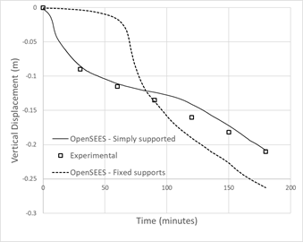
Lim, L., Buchanan, A., Moss, P., & Franssen, J. (2004). Numerical modelling of two-way reinforced concrete slabs in fire. Engineering Structures, 26, 1081–91. https://doi.org/10.1016/j.engstruct.2004.03.009
This page is created by Mhd Anwar, 2020