Hybrid simulation of Cardington Plane Frame Test
Developed by Dr Xuesong Cai and Dr Liming Jiang
Introduction
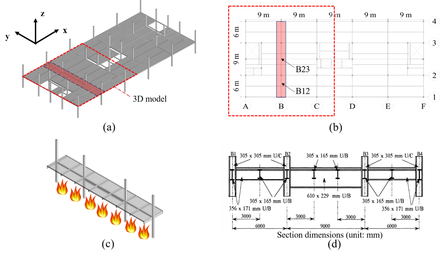
Figure 1 shows the test configuration, which was tested at Cardington. The test was conducted in an eight-storey steel-frame structure, built in the BRE Cardington facility. The floor plan was 45 m long and 21 m wide and was spread over five 9 m longitudinal bays along the x-direction and three bays along the y-direction as shown in Fig. 2b. In the center of the floor plan, there was a 9.0 m×2.5 m lift core and two 4.0 m×4.5 m stairwells. The composite floor slabs were 130 mm thick with 55 mm deep ribs. More details of this test structure can be found in the literature [6]. To apply the fire loading, the furnace was constructed at the lower floor (Floor 3) of a heating area of 21.0 m×2.5 m primarily heating the Grid B frame. As shown in Table 1, the sections of the primary beams were 610×229×101UB, 356×171×51UB, and 356×171×51UB, while the section for the secondary beam was 305×165×40UB. The columns had the section of 305×305×137UC. The experimental furnace was heated with eight burners on the third floor and the temperature was nearly uniformly distributed. The primary beams and secondary beams as well as the floor slab were unprotected. The internal columns were enclosed in the furnace and were protected up to 200 mm below the beam-column connections.
| OpenSees Model | Type used for this example |
|---|---|
| Element | ShellNLDKGQThermal, DispBeamColumnThermal |
| Section | LayeredShellThermal, FiberSection3D |
| Material | CDPPlaneStressThermal, SteelECThermal, J2PlaneStressThermal |
| Thermal Loading | ShellThermalAction, with userdefined dat file |
Download: This Example Package
Model Geometry
Tcl scripts for model definition
#  units are mm, N, MPa, ton, and C

#  Column coordinates


# Model builder

model BasicBuilder -ndm 3 -ndf 6;

source DisplayPlane.tcl

source DisplayModel2D.tcl

source DisplayModel3D.tcl

#nodes#############################################################

logFile "Hybrid20210818_master.log"

# Load OpenFresco package

# -----------------------

# (make sure all dlls are in the same folder as openSees.exe)

loadPackage OpenFresco


# Execute

source sections.tcl

puts "loaded 'sections' correctly"

source nodes.tcl

puts "loaded 'nodes' correctly"

source constraints.tcl

puts "loaded 'constraints' correctly"


## Define the control point (Column B2)

#expControlPoint 1  -node 2817 3 disp

#expControlPoint 2  -node 2817 3 disp 3 force


expControlPoint 1 -node 2817 1 disp 2 disp 3 disp

expControlPoint 2 -node 2817 1 disp 2 disp 3 disp 1 force 2 force 3 force


expControlPoint 3 -node 2917 1 disp 2 disp 3 disp

expControlPoint 4 -node 2917 1 disp 2 disp 3 disp 1 force 2 force 3 force


#expControlPoint 1 -node 2817 1 disp

#expControlPoint 2 -node 2817 1 disp 1 force


## Define the test control method

#expControl SimFEAdapter 1 "127.0.0.1" 44000  -trialCP 1 -outCP 2

expControl SimFEAdapter 1 "127.0.0.1" 44000 -trialCP 1 -outCP 2

expControl SimFEAdapter 2 "127.0.0.1" 43000 -trialCP 3 -outCP 4

#expControl SimFEAdapter 2 "127.0.0.1" 44000 -trialCP 1 -outCP 2

## Define the transformation

expSetup NoTransformation 1 -control 1 -dir 2 4 1  -sizeTrialOut 6 6

expSetup NoTransformation 2 -control 2 -dir 2 4 1  -sizeTrialOut 6 6

#expSetup NoTransformation 1 -control 1 -dir 1  -sizeTrialOut 6 6

#expSetup NoTransformation 1 -control 1 -dir 1 2 3  -sizeTrialOut 6 6

#expSetup NoTransformation 1 -control 1 -dir 2 4 1 5 3 6  -sizeTrialOut 6 6


## Define the Test site

expSite LocalSite 1 1

expSite LocalSite 2 2

## End of OpenFresco


source elements.tcl


expElement beamColumn 200000 2801 2817 44 -site 1 -initStif\

9.1e5  0     0        0      0  0\

0      1054  0        0      0  0\

0      0     0        0      0  0\

0      0     0        3200    0  0\

0      0     0        0      0  0\

0      0     0        0      0  0\


expElement beamColumn 200001 2901 2917 44 -site 2 -initStif\

9.1e5  0     0        0      0  0\

0      1054  0        0      0  0\

0      0     0        0      0  0\

0      0     0        3200    0  0\

0      0     0        0      0  0\

0      0     0        0      0  0\


puts "loaded 'elements' correctly"

source loads.tcl
Output Results
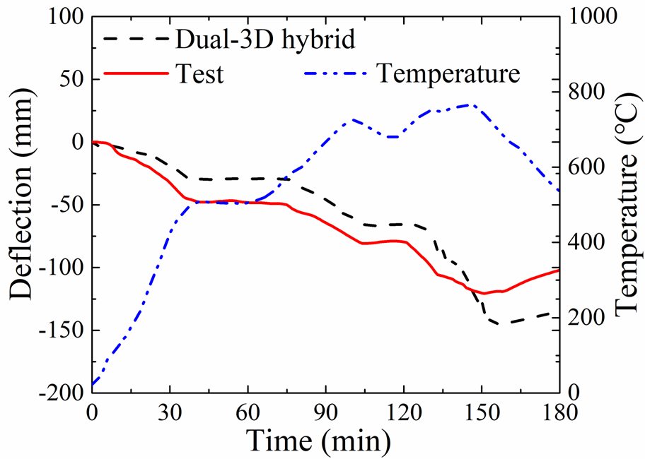
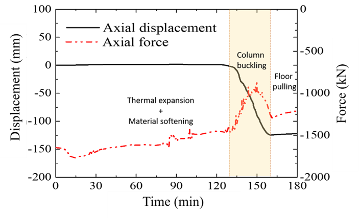
Using the Dual-3D hybrid simulation, the fire responses of Beam B12 and column are shown in the following figure
X. Cai, Liming Jiang*, J. Qiu, A. Orabi, C. Yang, G. Lou, M. Khan, Y. Yuan, G-Q. Li, A. Usmani. 2022. Dual-3D Hybrid Simulation of Steel Structures in Fires Using OpenSees and OpenFresco. Journal of Construction Steel Research.https://doi.org/10.1016/j.jcsr.2022.107511
This page is created by Liming Jiang, 2016