Comparision of material models: Steel01Thermal, Steel02Thermal and SteelECThermal using a restrained beam example
Developed by Domada Veera Venkata Ramakanth
Introduction
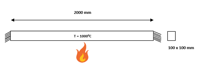
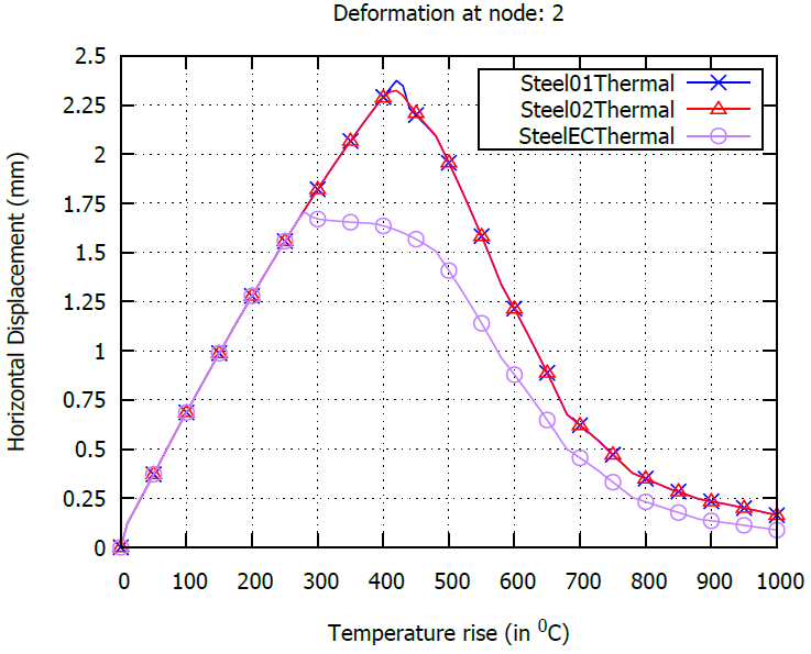
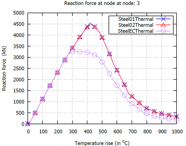
Figure-1 shows a restrained beam subjected to a temperature rise. The beam has been modelled using three existing steel models catering for thermal material degradation. The temperature load has been appl;ied on the left half portion of the beam. Displacement of the middle node and reaction at the right support have been compared in all three cases.
| OpenSees Model | Type used for this example |
|---|---|
| Element | DispBeamColumnThermal |
| Section | FiberSectionThermal |
| Material | Steel01Thermal, Steel02Thermal, SteelECThermal |
| Thermal Loading | Linear temperature rise over the left half of the member |
Download: This Example Package
Model Geometry
Tcl scripts for model definition
Restrained Beam model
  wipe;
  set s1 1;
  set s2 2;
  set s3 3;

  model BasicBuilder -ndm 2 -ndf 3

  # node $NodeTag $XCoord $Ycoord
  node      1         2000            0
  node      2         1000            0
  node      3            0            0

  # fix $NodeTag x-transl y-transl z-rot
  fix      1   1   1   1
  fix      3   1   1   1

  # Geometric Transformation
  geomTransf Linear 1
  geomTransf PDelta 2
  geomTransf Corotational 3

  #uniaxialMaterial Steel01Thermal $matTag $Fy $E0 $b <$a1 $a2 $a3 $a4>
  uniaxialMaterial  Steel01Thermal      1  500 2e+05 0.15


  #uniaxialMaterial Steel02Thermal $matTag $Fy $E0 $b $R0 $cR1 $cR2 <$a1 $a1 $a1 $a1>
  uniaxialMaterial Steel02Thermal 2 500 2e+05 0.15 20 0.925 0.15 0 1 0 1 0


  #uniaxialMaterial SteelECThermal $matTag <$steelType> $Fy $E0
  uniaxialMaterial  SteelECThermal      3  500 2e+05

  section fiberSecThermal 155 -GJ        10000 {

  #patch quad $matTag $numSubdivIJ $numSubdivJK $yI $zI $yJ $zJ $yK $zK $yL $zL
  patch quad $s1 10 10 -50.0 -50.0 50.0 -50.0 50.0 50.0 -50.0 50.0
  }


  # element dispBeamColumn $eleTag $iNode $jNode $numIntgrPts $secTag $transfTag
  element dispBeamColumnThermal      1      3      2  3    155  1   -mass        0
  element dispBeamColumnThermal      2      2      1  3    155  1   -mass        0


  recorder Node -file Node_displacements-s1.out -node 2 -dof 1 disp
  # recorder Node -file Node_rotations.out -time -nodeRange 1 3 -dof 3 disp
  recorder Node -file Node_forceReactions-s1.out -node 3 -dof 1 reaction
  # recorder Node -file Node_momentReactions.out -time -nodeRange 1 3 -dof 3 reaction
  # recorder Element -file DispBeamColumn_localForce.out -time -ele 1 2 localForce
  # recorder Element -file DispBeamColumn_basicDeformation.out -time -ele 1 2 basicDeformation
  # recorder Element -file DispBeamColumn_plasticDeformation.out -time -ele 1 2 plasticDeformation


  puts "Running interval 1\n"

  # Loads - Plain Pattern
  pattern Plain 100 Linear {
    eleLoad	-ele	1	-type	-beamThermal	1000	-50	  1000	 50.0

  }
  # recording the initial status

  record

  # Analysis options
  system BandGeneral
  numberer Plain
  constraints Transformation
  integrator LoadControl 0.01
  test NormDispIncr 0.001 50 2
  algorithm Newton
  analysis Static
  analyze 100
Output Results
Comparision of horizontal displacement of the middle node
Comparision of reaction force at the right side support
Closed form solution
The solution can be verified using a closed form expression as shown given below.
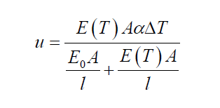
Here u is the horizontal displacement of middle node, Eo and E(T) are the elastic modulous at ambient and elevated temperature respectively
This page is created by D.V.V. Ramakanth, 2020