Restrained beam subjected to temperature rise
Developed by Dr Mustesin Khan and Dr Jian Jiang
Introduction
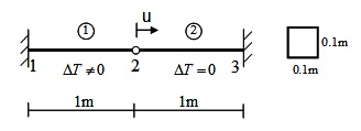
Figure E1-1 shows a 2m beam, only the left half of which is subjected to a uniform temperature increment from 0oC to 1000oC. The right half of the beam keeps ambient temperature and acts as a translational spring to restrain the displacement of the left part. Two beam elements are used in the model. Material class Steel01Thermal is used and the initial modulus of elasticity at 0oC is 200GPa.
| OpenSees Model | Type used for this example |
|---|---|
| Element | DispBeamColumn2DThermal |
| Section | FIberSection2DThermal |
| Material | Steel01Thermal |
| Thermal Loading | Beam2DThermalAction (uniform temperature rise) |
Download: This Example Package
Model Geometry
Tcl scripts for model definition
A. 2D model:
#define node

node 1 0 0;

node 2 2 0;

node 3 1 0;


#define boundary condition;

fix 1 1 1 1;

fix 2 1 1 1;

fix 3 0 1 1;


#define an elastic material with Tag=1 and E=2e11.

uniaxialMaterial Steel01Thermal 1 2e11 2e11 0.01;


#define fibred section; Two fibres: fiber $yLoc $zLoc $A $matTag

set secTag 1;

   section FiberThermal $secTag {

    fiber -0.025 0 0.005 1;

    fiber 0.025 0 0.005 1;

    };

#define coordinate transforamtion: geomTransf $type $TransfTag;

#three transformation types can be chosen: Linear, PDelta, Corotational)

geomTransf Linear 1 ;


#define beam element: dispBeamColumnThermal $eleTag $iNode $jNode $numIntgrPts $secTag $TransfTag;

#"numIntgrPts" is the number of integration points along the element;

#"TransfTag" is pre-defined coordinate-transformation;

element dispBeamColumnThermal 1 1 3 3 1 1;

element dispBeamColumnThermal 2 3 2 3 1 1;

pattern Plain 1 Linear {

eleLoad -ele 1 -type -beamThermal 1000 -50 1000 50

#eleLoad -ele 2 -type -beamThermal 0 -0.05 0 0.05

};
B. 3D model:
wipe;

#file mkdir Data;           # create data directory

model BasicBuilder -ndm 3 -ndf 6;# 2 dimension and 3 dofs per node

#source DisplayPlane.tcl;       # procedure for displaying a plane in model

#source DisplayModel2D.tcl;     # procedure for displaying 2D perspective of model


#define node

node 1 0 0 0;

node 2 2000 0 0;

node 3 1000 0 0;


#define boundary condition;

fix 1 1 1 1 1 1 1;

fix 2 1 1 1 1 1 1;

fix 3 0 1 1 1 1 1;


#define an elastic material with Tag=1 and E=2e11.

#uniaxialMaterial SteelECThermal 1 300 2e5 0.01;

uniaxialMaterial Steel01Thermal 1 1000 2e5 0.01;

#define fibred section; Two fibres: fiber $yLoc $zLoc $A $matTag

set secTag 1;

section FiberThermal $secTag {

    fiber -25 -25 2500 1;

    fiber -25 25 2500 1;

    fiber 25 -25 2500 1;

    fiber 25 25 2500 1;

 };


#define coordinate transforamtion: geomTransf $type $TransfTag;

#three transformation types can be chosen: Linear, PDelta, Corotational)

geomTransf Linear 1 0 1 0;


#define beam element:
#element dispBeamColumnThermal $eleTag $iNode $jNode $numIntgrPts $secTag $TransfTag;

element dispBeamColumnThermal  1 1 3 3 1 1;

element dispBeamColumnThermal  2 3 2 3 1 1;

#"numIntgrPts" is the number of integration points along the element;


#"TransfTag" is pre-defined coordinate-transformation;


#define output
recorder Node -file RBDFree31.out -time -node 3 -dof 1 disp;        # displacements of free nodes

recorder Element -file RBElement1Sec.out -time -ele 1 section 1 fiber -25 25 stressStrain

recorder Element -file RBElement1SecFibre.out -time -ele 1 section 2 fiber -25 25 TempElong;

recorder Element -file RBElement2LF.out -time -ele 2 localForce;


#define thermal load (i.e. temperature distribution in section)

#-beamThermal $T1 $LocY1 $T2 LocY2....; two temperature means uniform or linear temperature distribution

#T1=bottom temperature;T2=top temperature

pattern Plain 1 Linear {

eleLoad -ele 1 -type -beamThermal 1000 -50 1000 50

};
Output Results
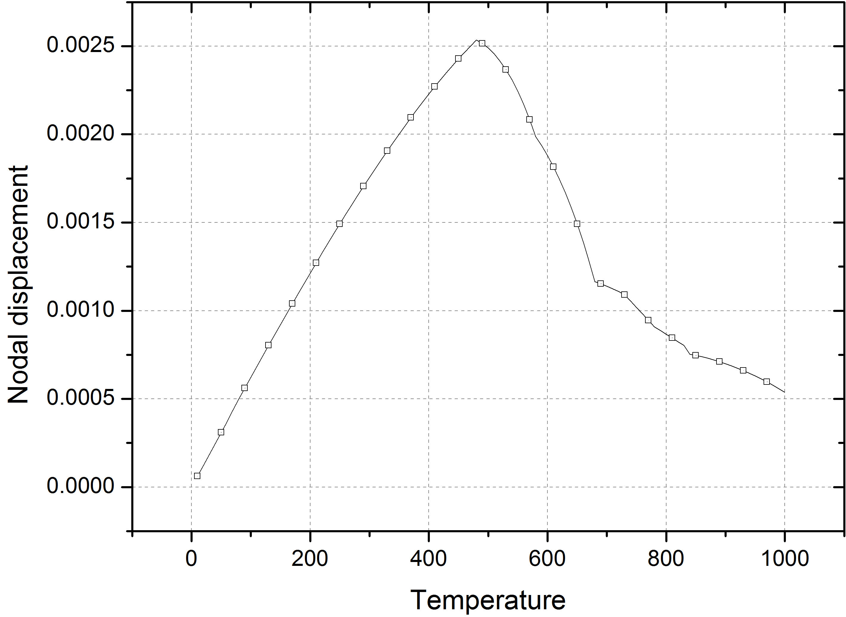
The varation of the mid-node displacement is shown in the following figure, where the node moves towards the right-hand direction due to thermal expansion and moves back because of material degradation
Jiang, J., & Usmani, A. (2013). Modeling of steel frame structures in fire using OpenSees. Computers & Structures, 118, 90–99. https://doi.org/10.1016/j.compstruc.2012.07.013
This page is created by Liming Jiang, 2016