A simply supported beam subjected to standard fire
Introduction
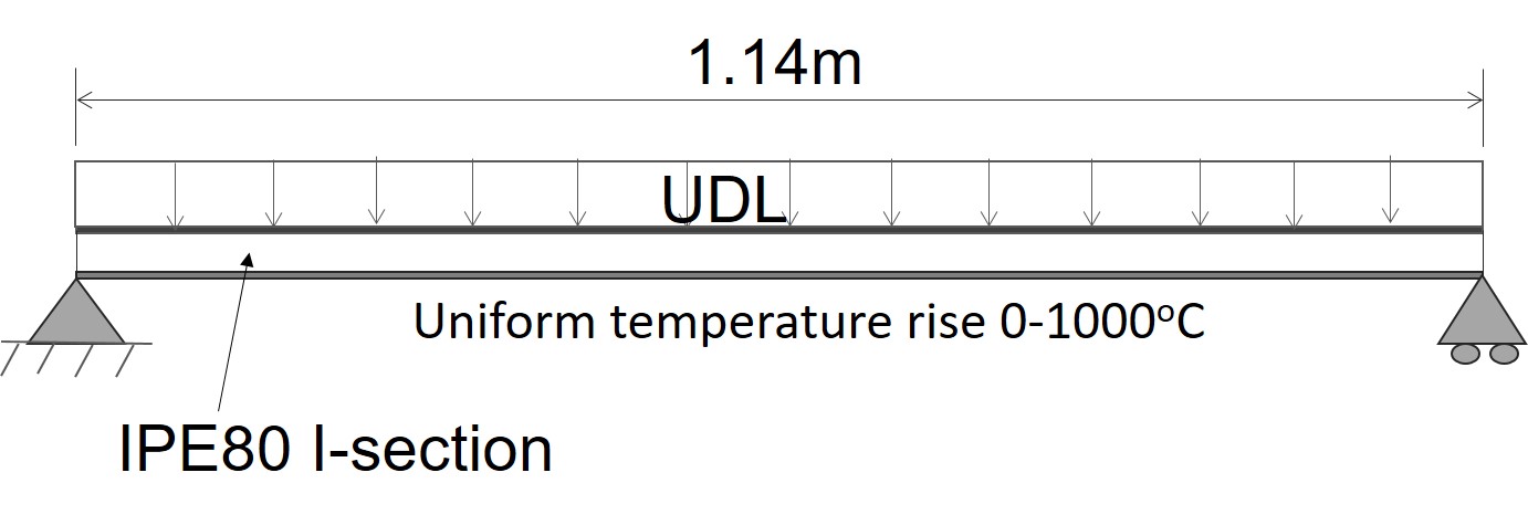
Figure E1-1 shows a 2m beam, only the left half of which is subjected to a uniform temperature increment from 0oC to 1000oC. The right half of the beam keeps ambient temperature and acts as a translational spring to restrain the displacement of the left part. Two beam elements are used in the model. Material class Steel01Thermal is used and the initial modulus of elasticity at 0oC is 200GPa.
Downloading the Example package here
A schematic plot of the Model
Tcl script for modelling a steel beam subjected to uniform temperture rise
# Units mm, MPa

#					y

#					|

#					|

#					|_________	x

#				   /

#				  /

#				 /z


wipe;

file mkdir WrapperData;

model BasicBuilder -ndm 2 -ndf 3;

source DisplayPlane.tcl;		# procedure for displaying a plane in model

source DisplayModel2D.tcl;		# procedure for displaying 2D perspective of model


#define node

set NumEles 2;

set BeamLen 1140.0;


set EleLen [expr $BeamLen/$NumEles]

for {set NodeID 0} {$NodeID <= $NumEles} {incr NodeID} {

set locX [expr $NodeID*$EleLen];

set NodeTag [expr $NodeID+1];

node $NodeTag $locX 0;

}

set EndNodeTag [expr $NumEles+1]

set MidNodeTag [expr $NumEles/2+1]

#define boundary condition;

fix 1 1 1 0;

fix $EndNodeTag 0 1 0;


uniaxialMaterial SteelECThermal 1 EC3 235 206000;


###########################################################################

proc Wsection { secID matID d bf tf tw nfdw nftw nfbf nftf} {

	# ###################################################################

	# Wsection  $secID $matID $d $bf $tf $tw $nfdw $nftw $nfbf $nftf

	# ###################################################################

	# create a standard W section given the nominal section properties

	# written: Remo M. de Souza

	# date: 06/99

	# modified: 08/99  (according to the new general modelbuilder)

	# input parameters

	# secID - section ID number

	# matID - material ID number

	# d  = nominal depth

	# tw = web thickness

	# bf = flange width

	# tf = flange thickness

	# nfdw = number of fibers along web depth

	# nftw = number of fibers along web thickness

	# nfbf = number of fibers along flange width

	# nftf = number of fibers along flange thickness


	set dw [expr $d - 2 * $tf]

	set y1 [expr -$d/2]

	set y2 [expr -$dw/2]

	set y3 [expr  $dw/2]

	set y4 [expr  $d/2]


	set z1 [expr -$bf/2]

	set z2 [expr -$tw/2]

	set z3 [expr  $tw/2]

	set z4 [expr  $bf/2]


	section fiberSecThermal  $secID  {

   		#                     nfIJ  nfJK    yI  zI    yJ  zJ    yK  zK    yL  zL

   		patch quadr  $matID  $nfbf $nftf   $y1 $z4   $y1 $z1   $y2 $z1   $y2 $z4

   		patch quadr  $matID  $nftw $nfdw   $y2 $z3   $y2 $z2   $y3 $z2   $y3 $z3

   		patch quadr  $matID  $nfbf $nftf   $y3 $z4   $y3 $z1   $y4 $z1   $y4 $z4

	}

}


Wsection  1 1 80 46 5.2 3.8 16 2 16 2;

set d 80;

#Wsection 1 1 320 160 10 10 8  2 8 2;

#define coordinate transforamtion: geomTransf $type $TransfTag;

#three transformation types can be chosen: Linear, PDelta, Corotational)

geomTransf Corotational 1 ;


#define beam element: dispBeamColumnThermal $eleTag $iNode $jNode $numIntgrPts $secTag $TransfTag;

#"numIntgrPts" is the number of integration points along the element;

#"TransfTag" is pre-defined coordinate-transformation;

for {set eleID 1} {$eleID<= $NumEles} {incr eleID} {

	set NodeTag0 $eleID;

	set NodeTag1 [expr $eleID+1];

	element forceBeamColumnThermal $eleID $NodeTag0 $NodeTag1 5 1 1;

}


#define output

set MidSpanNode [expr 1+$NumEles/2];

set MidSpanEle [expr $NumEles/2];


recorder Node -file N_MidSpan_DOF.out -time -node $MidSpanNode -dof 2 disp;

recorder Element -file Element1Sec40T.out -time -ele $MidSpanEle section 1  fiber 40 0 TempElong;

recorder Element -file Element1Secm40T.out -time -ele $MidSpanEle section 1  fiber -40 0 TempElong;

recorder Element -file EleSecSSm40.out -time -ele $MidSpanEle section 1  fiber -40 0 stressStrainTangent;

recorder Element -file EleSecSS40.out -time -ele $MidSpanEle section 1  fiber 40 0 stressStrainTangent;

recorder Element -file EleSecSSm10.out -time -ele $MidSpanEle section 1  fiber -10 0 stressStrainTangent;

recorder Element -file EleSecSS10.out -time -ele $MidSpanEle section 1  fiber 10 0 stressStrainTangent;

recorder Element -file EleForceSec1.out -time -ele $MidSpanEle section 1 forces;

#display 2D deformation shape

set ViewScale 0.00001;	# scaling factor for viewing deformed shape, it depends on the dimensions of the model

DisplayModel2D DeformedShape $ViewScale;


set Load 19123;

set mLoad [expr $Load*0.2];

#define Uniform load

puts "Now applying uniform load  ";

puts $mLoad;


pattern Plain 1 Linear {


   load	$MidSpanNode  0 $mLoad  0;


};


constraints Plain;

numberer Plain;

system BandGeneral;
test NormDispIncr 1e-3 100 1;

algorithm Newton;

integrator LoadControl 0.1;

#integrator DisplacementControl $EndNodeTag  1  1;

analysis Static;

analyze 10;


loadConst -time 0.0

puts "temperature loading"

# Define Thermal Load

set minusHalfD [expr -$d/2]

set HalfD [expr $d/2]


pattern Plain 2 Linear {


eleLoad -range 1 $NumEles -type -beamThermal 1000 $minusHalfD 1000 $HalfD


}


constraints Plain;

numberer Plain;

system BandGeneral;

test NormUnbalance 1.0e-4 50 1;

algorithm Newton;

integrator LoadControl 0.01;

analysis Static;

analyze 100;

wipe;
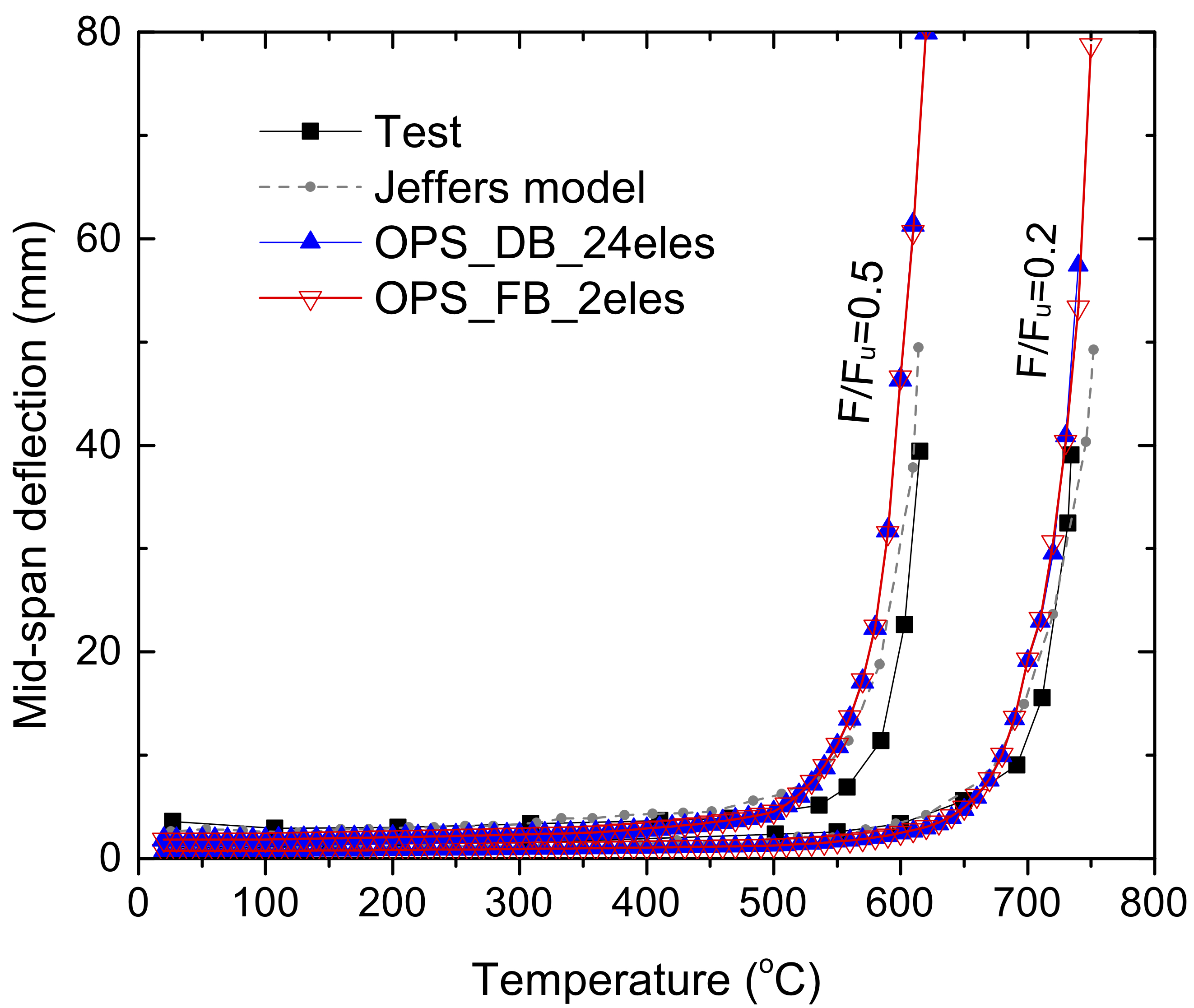
Displacement of mid-node
The varation of the mid-node displacement is shown in the following figure, where the node moves towards the right-hand direction due to thermal expansion and moves back because of material degradation
Reference
This page is created by Liming Jiang, 2016