Commands for Using Sifbuilder
This page lists the available commands for modelling structures in fire using SIFBuilder in OpenSees. SIFBuilder is an integrated tool developed in OpenSees, of which the development is still ongoing. Therefore the commands may be added as time goes by.
Basic Commands
SIFBuilder
SIFBuilder command is used to activate the SIFBuilder module, which is followed by frame or plane and other options. Thses options are associated with different model type to creat a 3D frame model or 2D plane frame models. Here the command can be written as:
SIFBuilder

or

SIFBuilder frame
BuildModel
BuildModel command is used to set up the finite element model for the structure. So the command keyword is followed by the model mesh control information, which may be the model type such as elastic or dynamic (in the future). If the -MeshCtrl or MeshCtrl is detected, there should be two or three parameters following this keyword to specify the number of elemets for each structural member along x, y, z axis. After this, an extra option is provided for defining pinned connections at the beam-column joints, which enables that the all the primary beams are pinned to the continuous columns. The command is written as follows:
SIFBuilder

or

SIFBuilder frame
Geometry Commands
SIFXBay/SIFYBay/SIFStorey
SIFXBay command is used to define the distribution of bays along global x axis. The XBay dimension is defined directly following the command and being listed as a numbe of variables, which is written in the following form:
SIFXBay $XBay1 <$XBay2 $XBay3..>
SIFZBay $ZBay1 <$ZBay2 $ZBay3..>

SIFStorey $Storey1 <$Storey2 $Storey3..>
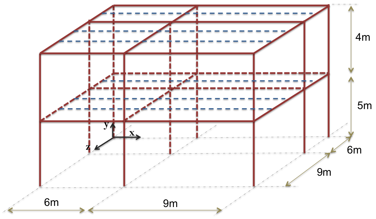
SIFXBay 6 9;

SIFYBay 6 9;

SIFStorey 5 4;
AddMaterial
AddMaterial command is used to create a structural material, such as concrete and steel and PFP materials:
AddMaterial $MatType $MatTag -type $MatSubType $MatPar1 <$MatPar2 $MatPar3 $MatPar4..>
Currently it's possible to define masterials such as steel, concrete in accordance to Eurocodes. Commands may be written as:
AddMaterial  steel   1   -type EC3  2.75e8 2e11;

AddMaterial concrete 2 -type EC2 0.0 30e6;
AddSection
AddSection command is used to create a structural member section, such as rectangular and I sections:
AddSection $SectionType $SecTag $MatTag $MatPar1 <$MatPar2 $MatPar3 $MatPar4..>
Currently it's possible to define structural sections such as rectangular or I sections. Theses commands may be written as:
AddSection  Rect   1  2  0.4 0.4 0.4 0.4;

AddSection  ISection   2  1 0.355 0.1715 0.0074 0.0115;;
AssignSection
AssignSection command is used to assign sections to the specified structural members, which include Xbeams, Zbeams, Columns, Slabs. And it also allows the user to change the sections for the sepcific members which are identified through XBay and ZBay locations.
AssignSection $MemberGroup $SecTag <-XBay $XBayTag> <-ZBay $ZBayTag> <-Storey $StoreyTag>
A few examples are shwon as below:
AssignSection Xbeams 3 ;

AssignSection Zbeams 1 ;

AssignSection Zbeams 1 -ZBay 1;

AssignSection Zbeams 2 -ZBay 2;

AssignSection columns 4;

AssignSection slabs 5;
Basic Commands
SetBC
SetBC command is responsible to define the boundary conditions of the SIFModel. Currently the boundary conditions are defined on SIFJoints which are selected according to their global coordinates. Two types of joint connection can be assigned: a pinned joint or a fixed joint. The global coordinates are specifed in terms of locx, locy, and locz which are corresppinding to the x,y,z coordinate. Notice that each keyword can be written as locx, Locx or -Locx, and it is followed by lower bound and upper bound of the coordinate or a single specified value of the coordinate.
SetBC -pinnedJoint -Locx $locxLB <$locxUB> <-Locy $locyLB <$locyUB> > <-Locz $loczLB <$loczUB> >

SetBC -fixedJoint -Locx $locxLB <$locxUB> <-Locy $locyLB <$locyUB> > <-Locz $loczLB <$loczUB> >
An example of using SetBC is shown as below, which is intending to create fixed connections at the base of the structure.
SetBC fixedJoint -Locy 0;
AddLoad
AddLoad command is used to apply mechanic load which includes point loads on SIFJoints, distributed loads on SIFMembers. The prototype of defining loads using this command is shown as below:
AddLoad -Joint $JointTag -load $loadVal1 <$loadVal2> <$loadVal3> <$loadVal4> <$loadVal5> <$loadVal6>

AddLoad -Member AllSlabs -load $loadVal1 <$loadVal2> <$loadVal3>

AddLoad -Member AllBeams -load $loadVal1 <$loadVal2> <$loadVal3>
An example of using AddLoad is shown as below, which will apply a point load on the node primarily assigned to the SIFJoint tagged as 2202, and a UDL on all the slabs.
AddLoad -joint 2202 -load 0 600000 0;

AddLoad -member allslabs -load 0 -6000 0;
This page is created by Liming Jiang, 2016