Thermal Action Commands for Thermo-Mechanical analysis in OpenSees
This page introduces the developed commands for performing thermo-mechanical analysis in OpenSees.
BeamThermal(2D)
This class is created as a subclass of abstract class ElementalLoad to define a thermal field which stores the termperature distribution (history) across a beam type section.Currently, two different approaches are recommended to define thermal action for beamcolumn element as a longitudinally uniform elemental load.
A. In-line temperature definition
The in-line temperature would accept 2,5,9 temperature data points to set up multiple temperature zones which are up to 8 zones for 2D beamcolumn element. It could be applied either with linear patterns or fire load patterns, and the load control integrator should be specified in the analysis. Typical commands may follow the form shown as below
eleLoad -ele $eleTag -type -beamThermal $T1 $y1 $T2 $Y2
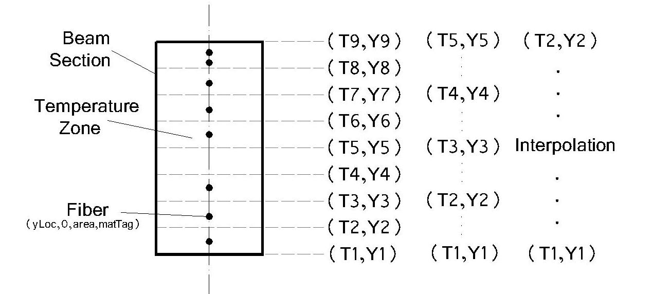
B. Using external temperature data file
To define a history of temperature vration across the section, it is possible to import the temperature data from an external file which should be presented in the format shown as below:
$time1 $T11 $T12 $T13 $T14 $T15 $T16 $T17 $T18 $T19

$time2 $T21 $T22 $T23 $T24 $T25 $T26 $T27 $T28 $T29

$time3 $T31 $T32 $T33 $T34 $T35 $T36 $T37 $T38 $T39

...
..
where the first column is to specify timesteps, and the second to tenth columns are temperatures corrsponding to each time step and zone boundaries. To use external file, the command can be written as:
eleLoad -ele $eleTag -beamThermal -source $fileName $Y1 $Y2 < $Y3 ... $Y9>
An example of using beam thermal action for 2D beam elements are presented as below:
pattern Plain 1 Linear {

    eleLoad -range 1 6 -type -beamThermal 600 -150 500 150;

}
The above script is to define a linear distribution of termperatures through the depth from 600C at the bottom (y=-150,in local cordinate system) to 500C at the top (y=150). A linear load pattern is used here which indicates the real temperatures applied are these final ones multiplied by load factors which are controled by analaysis parameters
When an external temperature history file is available, the script may look like:
pattern Plain 1 Linear {

    eleLoad -range 1 6 -type -beamThermal -source temp1.dat -150 150;

}
The above definition is quite handy for beams that are subjected to real fires, where it is even possible to produce the ready-to-use temperature data from heat transfer analysis module in OpenSees.
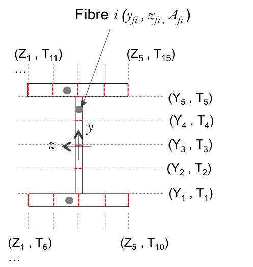
BeamThermal(3D)
BeamThermal command in a context of 3D analysis is used to define temperature field. which shall be defined as:
eleLoad -ele $eleTag -beamThermal -source $fileName $y1 $y2 $z1 $z2;
The above command is used for 3D I-section beam. An example is shown as below
eleLoad -ele 2 -beamThermal -source data.dat -0.25 0.25 -0.15 0.15
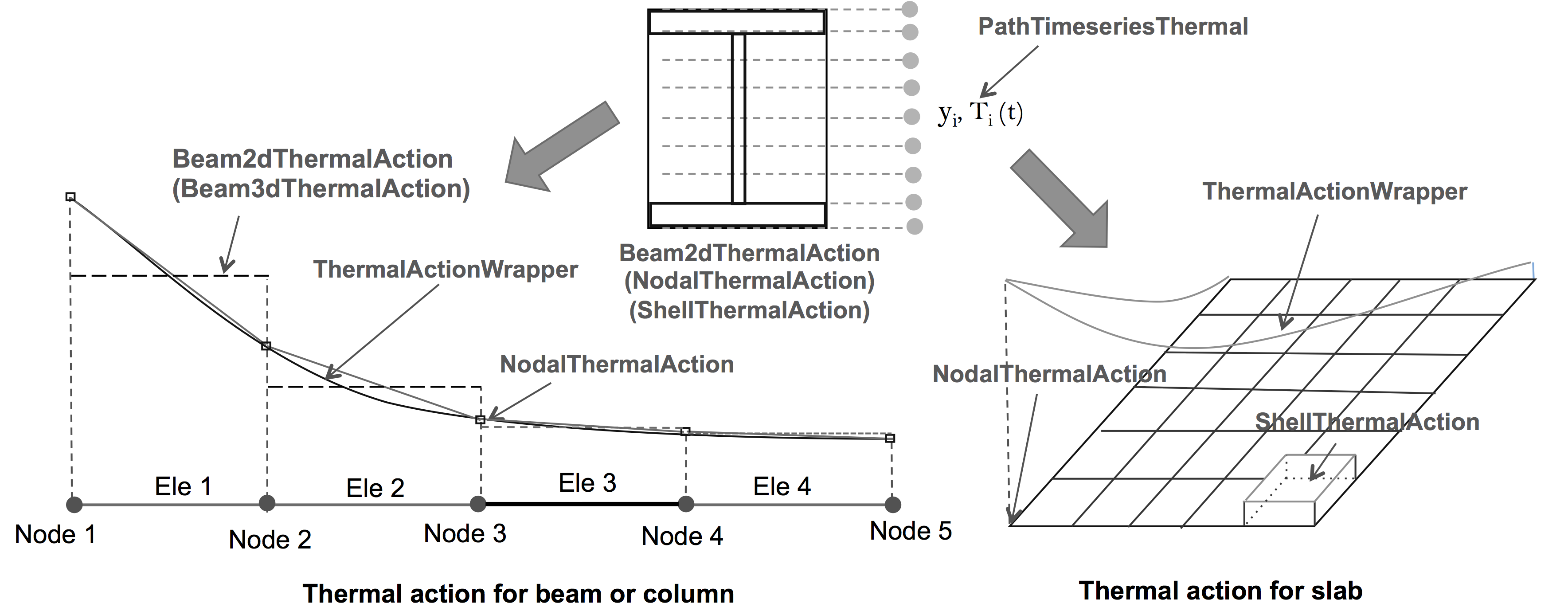
Nodal Thermal Action
Thermal action can be defined on nodes using load command as the NodalThermalAction is an extended nodal load. The folling command could be used to define a linear gradient or uniform distribution of temperatures through depth of a section. The temperatures will be multiplied by load factors obtained from analysis control.
load $nodeTag -nodalThermal $T1 $y1 $T2 $y2;
More commonly, it might be of users's interest to define temperatures in an external file. The following commands are recommended:
load $nodeTag -nodalThermal -source $fileName $y1 $y2;

load $nodeTag -nodalThermal -source $fileName $y1 $y2..$y9;

load $nodeTag -nodalThermal -source $fileName $y1 $y2 $z1 $z2;
Among the above definitions, the first one is to specify the bottom y coordinate and the top coordinate, where the y coordinates are equally interpolated between them.
The second definition is to specify 9 y coordinates, while the last one is used for 3D I-section with two z coordinates. These definitions are similar to beam sections.An example is shown as below:
set minusHalfD -0.125;

set HalfD 0.125;

load 1 -nodalThermal 800 $minusHalfD 400 $HalfD;
ThermalActionWrapper
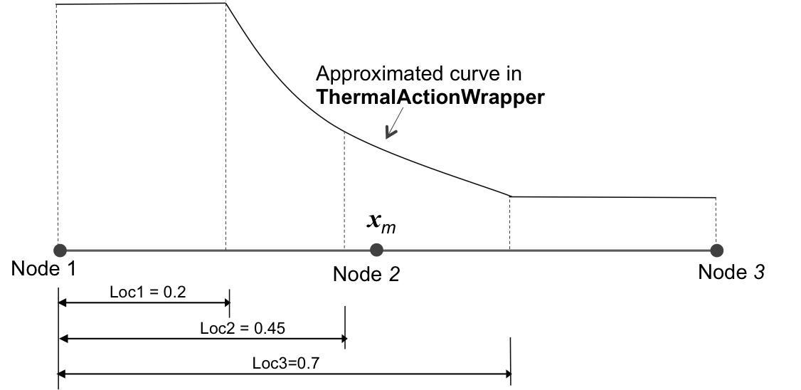
ThermalActionWrapper is introduced to describe the temperature variation along the member length, providing the fibre temperature at the integration points. Nodal Thermal Actions are wrapped up into the class, which enables a different form of interpolation to be performed to determine the temperature profile at each section (integration point) of the beam element. For instance, assuming a beam as shown in Figure 3 has been discretised into n nodes and n-1 elements, an arbitrary beam element among them may be between node $m$ and node m+1.
Different interpolations are provided with ThermalActionWrapper, which should always work nodal thermal action. Commands should follow the format shwon as below:
eleLoad -range $startEleTag $EndEleTag -type -ThermalWrapper -nodeLoc $NodeTag1 $loc1 $NodeTag2 $loc2 <$NodeTag3 $loc3..>;
An example of using ThermalActionWrapper is shown as below:
set MiddleTag 6;

set EndTag 11;

load 1 -nodalThermal 800 -0.2 400 0.2;

load $MiddleTag -nodalThermal 400 -0.2 200 0.2;

load $EndTag -nodalThermal 0 -0.2 0 0.2;

eleLoad -range 1 10 -type -ThermalWrapper -nodeLoc 1 0.2 $MiddleTag 0.45 $EndTag 0.7;
This page is created by Liming Jiang, 2016